
CNC Machining Services: Machining Datum vs Assembly Datum
Datum selection is one of the most important elements in CNC Machining Services because the way a component is positioned, machined and inspected directly affects dimensional relationships between its features. A machining datum is primarily used to establish the workpiece position during manufacturing, while an assembly datum defines how the finished component is located or oriented relative to another component. When these two reference systems are not properly coordinated, a part may meet individual dimensional requirements but still create positioning, alignment or assembly problems.
Machining datum selection becomes particularly important for components containing multiple holes, mounting surfaces, stepped features, pockets, shafts, bores and precision locating surfaces. During CNC production, the workpiece may require several setups, and every additional setup introduces another opportunity for datum transfer error. The relationship between the original machining datum, secondary datums and final assembly references therefore needs to be considered during process planning.
This article explains the differences between machining datums and assembly datums and examines how datum selection influences CNC Machining Services. It covers datum hierarchy, fixture positioning, multiple setups, datum transfer, hole positioning, inspection, geometric tolerances and common engineering failures. The goal is to help engineers and purchasing teams understand how datum strategy contributes to dimensional consistency and assembly performance.
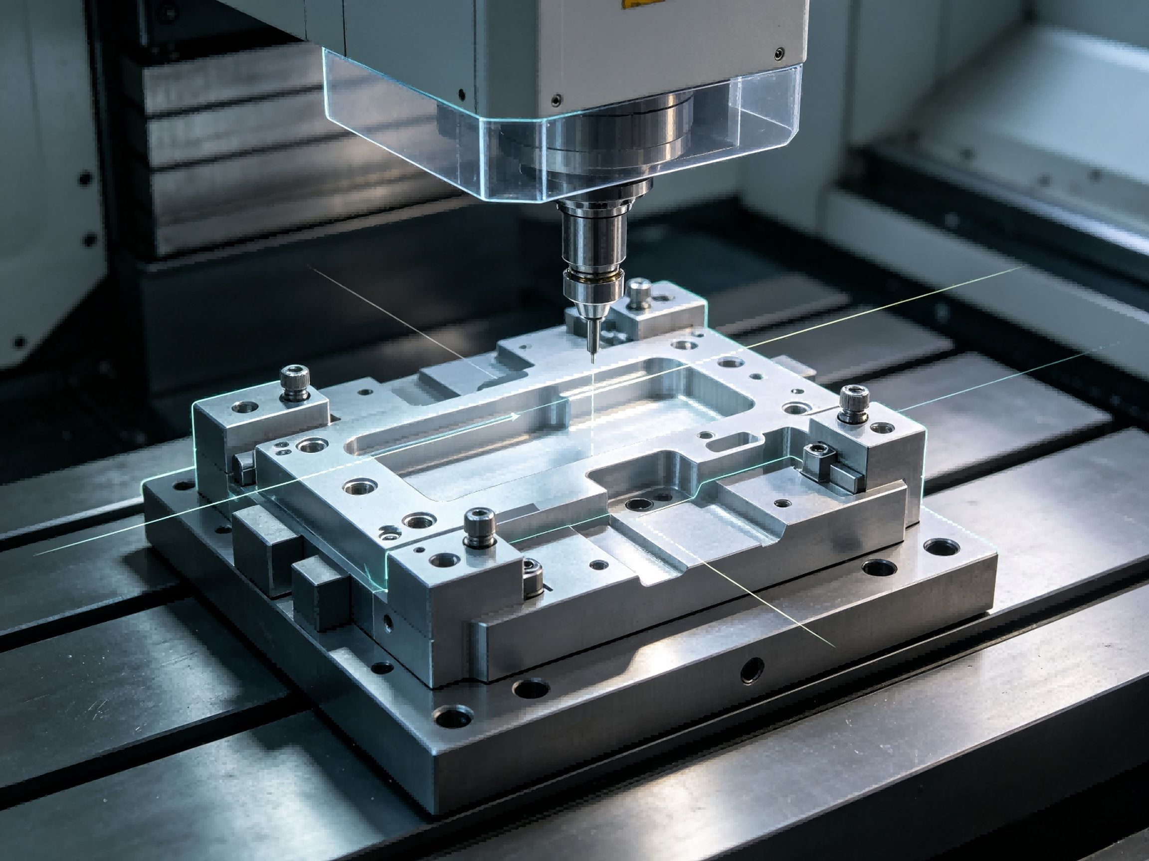
A datum is a theoretically exact reference used to establish the location or orientation of a feature, surface or coordinate system. In practical CNC Machining Services, datums provide the basis for positioning the workpiece, programming machining operations and evaluating dimensional relationships.
A datum is not simply a visible line or physical mark on a component. It represents a reference framework from which other dimensions or geometric requirements are established.
For example, a flat mounting surface may establish the primary orientation of a component, while a perpendicular side surface controls lateral positioning. A third feature may then control rotation or locate the component along another direction.
| Datum Concept | Typical Function | Manufacturing Importance |
|---|---|---|
| Primary datum | Establishes the main orientation | Controls initial workpiece positioning |
| Secondary datum | Controls another directional relationship | Improves repeatable location |
| Tertiary datum | Completes positional constraint | Controls remaining degrees of freedom |
| Assembly datum | Locates the component in an assembly | Controls mating and functional alignment |
pemVerify all parameters against current test reports and applicable standards before use in specifications.emp
The key difference is their purpose.
A machining datum is selected to establish a stable and repeatable position during manufacturing. It allows CNC machines and fixtures to locate the workpiece consistently so that dimensions can be produced relative to a controlled reference.
An assembly datum, by contrast, represents the functional reference used when the finished component is installed into an assembly. It may correspond to a mounting face, shaft axis, locating hole, bearing seat, flange surface or another feature that determines how the component interacts with surrounding parts.
These two datum systems may be identical, but they do not have to be. When they are different, the process engineer must establish a controlled relationship between them.
| Characteristic | Machining Datum | Assembly Datum |
|---|---|---|
| Primary purpose | Position the workpiece during machining | Position the finished part during assembly |
| Typical reference | Fixture surface or machined reference feature | Functional mounting or locating feature |
| Main concern | Repeatability and process stability | Fit, alignment and functional positioning |
| Controlled by | Fixture and machining process | Assembly design and mating components |
pemVerify all parameters against current test reports and applicable standards before use in specifications.emp
Datum selection determines how dimensional relationships are created during machining. If a critical mounting surface is used as the reference for machining a hole pattern, the hole locations will be controlled relative to that surface.
If the same hole pattern is instead machined from another surface whose relationship to the mounting surface has manufacturing variation, the final hole position relative to the assembly surface may accumulate additional error.
This is one reason a part can satisfy individual dimensional tolerances while still experiencing an assembly problem. Each dimension may be within its specified range, but the accumulated relationship between features may not provide the required functional positioning.
A workpiece can move in multiple directions before it is fully constrained. Datum systems and fixture elements are used to restrict these movements and establish a repeatable position.
The primary datum generally establishes the main plane of orientation. A secondary datum controls movement in another direction and helps establish rotational positioning. A tertiary datum completes the locating scheme.
In practical CNC Machining Services, this concept is implemented through fixture surfaces, locating pins, stops, clamps and other workholding features.
The objective is not simply to clamp the workpiece tightly. The objective is to locate the component accurately and repeatably while minimizing deformation and unnecessary variation.
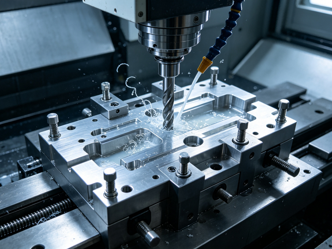
A machining datum should provide sufficient contact area and stability. A weak, narrow or irregular surface may create positioning variation or cause the component to move under machining forces.
When possible, using a surface or feature that is also important during assembly can reduce the number of datum transformations between manufacturing and final use.
A datum may change during the manufacturing process if material is removed from its surface. Process planning should determine when a reference surface becomes sufficiently accurate to serve as a reliable datum.
For repeated production, the datum should allow the component to be loaded in a consistent position. A theoretically correct datum is not useful if operators cannot reproduce the same physical setup.
Fixture design translates the theoretical datum system into a physical manufacturing process. The fixture must provide appropriate locating surfaces while allowing cutting tools to access the required features.
A poor fixture can introduce several problems. Excessive clamping force may deform the component, while insufficient support may allow vibration or movement. A locating pin may also introduce unwanted clearance variation if the mating hole is not suitable for the locating function.
For thin-wall or flexible components, fixture design becomes even more important because clamping forces can change the geometry during machining.
| Fixture Element | Typical Function | Potential Issue |
|---|---|---|
| Support surface | Establishes primary positioning | Surface contamination or instability |
| Side stop | Controls lateral location | Incorrect contact or movement |
| Locating pin | Controls hole-based positioning | Clearance or hole variation |
| Clamp | Holds the workpiece in position | Excessive deformation |
| Support point | Reduces vibration and deflection | Improper placement |
pemVerify all parameters against current test reports and applicable standards before use in specifications.emp
Assembly datums are determined by how the component interacts with the larger system. A mounting face may determine the vertical position of a component, while a bore may establish a rotational axis.
For example, a machined housing may contain a mounting flange, a central bore and several bolt holes. The flange may establish the primary assembly reference, the bore may control the functional axis, and the bolt-hole pattern may secure the component to another structure.
In this situation, the manufacturing process should pay particular attention to the geometric relationship between these features rather than treating every dimension independently.
Multi-setup machining is one of the most common situations in which datum transfer becomes important. A component may be machined on one side during the first setup and then repositioned to machine the opposite side.
If the second setup uses a different physical reference, the relationship between the two setups depends on the accuracy of the datum features and fixture positioning.
Every transfer can introduce variation. For this reason, CNC Machining Services should minimize unnecessary setup changes when the component geometry and tooling access allow it.
Establish the initial workpiece datum.
Machine the reference surfaces or features required for later operations.
Inspect the reference features when necessary.
Reposition the component using controlled locating features.
Establish the new machine coordinate relationship.
Machine secondary features from the transferred datum.
Inspect the final relationship between critical features.
Hole patterns are particularly sensitive to datum strategy because several holes may need to align with corresponding features on another component.
Suppose a mounting pattern is positioned relative to one surface while the actual assembly references the opposite surface. Any variation in the relationship between those two surfaces can influence the final hole location relative to the assembly.
This does not necessarily mean the machining process is incorrect. It means that the drawing, datum structure and manufacturing process need to be coordinated so that the required functional relationship is directly controlled.
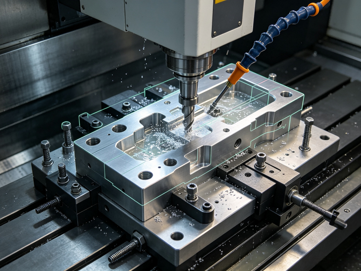
For shafts, pins and rotational components, the functional datum is often related to an axis. Bearing seats, shoulders, grooves and threaded features may all need to maintain controlled relationships with that axis.
During CNC Machining Services, the process may use a chuck, collet, center or other workholding method to establish rotational positioning. The final inspection then needs to verify the relationship between diameters, shoulders and other features.
When several diameters must share a common axis, changing workholding methods unnecessarily can increase the risk of concentricity or runout variation.
For prismatic components, datum systems commonly involve flat surfaces, side faces and locating holes. The machining sequence should establish stable references before producing critical features that depend on them.
A typical sequence may begin with creating a reliable base surface, followed by a perpendicular reference surface and then additional holes, pockets or profiles.
The exact sequence depends on the component geometry and drawing requirements. There is no universal datum strategy that is suitable for every CNC machined component.
Geometric dimensioning and tolerancing provides a structured way to define relationships between features and datums. Position, perpendicularity, parallelism, flatness and other geometric requirements can depend on a defined datum reference framework.
This means that CNC Machining Services should not evaluate only the numerical tolerance of individual dimensions. The complete datum structure should be understood before developing the manufacturing process.
For example, a hole may have an acceptable diameter but still fail its functional requirement if its position relative to the assembly datum is incorrect.
A hole may meet its diameter tolerance but be positioned incorrectly relative to a mounting surface. This often indicates that size control and positional control were treated as separate issues.
If a fixture references a rough or unstable surface, workpiece positioning may vary between setups. A controlled datum surface may need to be machined first.
Repeatedly transferring dimensions from one feature to another can accumulate variation. Critical relationships should be controlled from an appropriate reference whenever practical.
A manufacturing fixture may use a convenient surface that is different from the drawing's functional datum. This can be acceptable in some processes, but the relationship between the two references must be controlled.
Flexible components may deform during clamping. Once released, the component can partially return to its original shape, causing dimensional differences between in-fixture and free-state measurements.
Precision CNC machining requires particular attention to datum consistency because small positioning errors can become significant when several features must maintain tight geometric relationships.
A practical process should establish a clear chain of references from raw material through rough machining, semi-finishing, finishing and inspection. Critical surfaces should be machined in an order that reduces unnecessary reference changes.
When a component requires several setups, process engineers should determine which machined features can serve as reliable secondary datums for subsequent operations.
Prototype and low-volume components may use simpler fixtures than high-volume production parts, but datum planning remains important. Manual fixture adjustments or flexible workholding can increase variation if reference conditions are not clearly defined.
For prototype parts, engineers can use the first completed component to verify whether the selected machining datum produces the required assembly relationships. If changes are required, they can be incorporated into the process before repeated production begins.
This approach can reduce the risk of discovering datum-related assembly problems after a larger production batch has been completed.
Inspection should verify not only the dimensions of individual datum features but also their geometric relationships. Depending on the component, inspection may include surface flatness, perpendicularity, parallelism, hole position, concentricity-related characteristics and other specified geometric requirements.
A CMM can be useful for evaluating complex datum relationships because it can establish a coordinate system from defined reference features and measure multiple characteristics within the same reference framework.
| Inspection Focus | What It Evaluates | Why It Matters |
|---|---|---|
| Datum surface | Size and geometric condition | Provides a stable reference |
| Datum perpendicularity | Angular relationship | Controls feature orientation |
| Hole position | Location relative to datums | Supports assembly alignment |
| Feature-to-feature relationship | Relative geometry | Controls functional positioning |
| CMM coordinate system | Multiple feature relationships | Provides structured inspection data |
pemVerify all parameters against current test reports and applicable standards before use in specifications.emp
Identify the functional assembly references from the engineering drawing.
Separate machining datums from assembly datums when their functions differ.
Select stable and repeatable machining references.
Establish primary, secondary and tertiary locating conditions where appropriate.
Minimize unnecessary datum transfers between setups.
Use functional machined features as secondary references when practical.
Control fixture locating surfaces and locating elements.
Consider clamping deformation for thin or flexible components.
Inspect critical datum relationships instead of checking only individual dimensions.
Verify the final component against the assembly reference system.
| Engineering Item | Question to Confirm |
|---|---|
| Assembly reference | Which surfaces or axes determine the functional position? |
| Machining reference | Which surfaces provide repeatable workpiece positioning? |
| Datum relationship | Is the relationship between machining and assembly datums controlled? |
| Fixture design | Does the fixture reproduce the intended datum system? |
| Setup count | Can unnecessary repositioning be reduced? |
| Hole patterns | Are critical holes located from the correct functional reference? |
| Inspection | Are datum-related geometric requirements verified? |
pemVerify all parameters against current test reports and applicable standards before use in specifications.emp
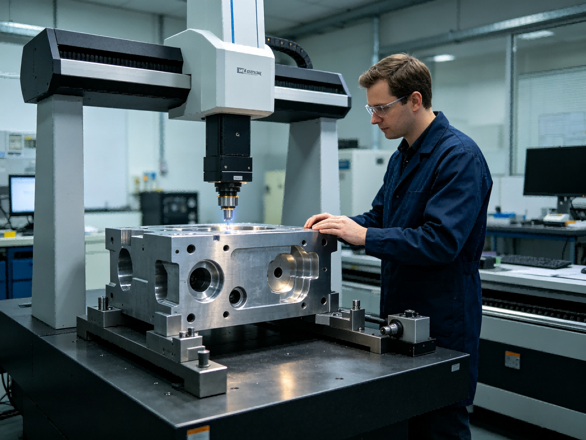
When evaluating CNC Machining Services, engineers and purchasing teams should ask how the manufacturer interprets the drawing datums, how the workpiece is located during each setup, and how critical assembly relationships are inspected. A supplier should be able to explain the relationship between fixture references, machining datums and final inspection datums.
Dongguan city Jifan Precision Machinery Co., Ltd provides CNC machining, custom prototyping and customized production capabilities supported by automated production lines and engineering support. For specific projects, datum strategy should be confirmed from the actual engineering drawings, material, tolerances, feature geometry and assembly requirements.
A machining datum is primarily used to position and orient a workpiece during manufacturing, while an assembly datum represents the functional reference used to locate the finished component in an assembly.
Yes. Using the same functional reference for manufacturing and assembly can simplify process control when the geometry and workholding conditions allow it.
Each setup change can introduce positioning variation. Controlled datum transfer helps maintain the geometric relationship between features machined in different setups.
The fixture physically establishes the workpiece position. Locating surfaces, pins, stops, clamps and supports must provide repeatable positioning without introducing excessive deformation.
Individual dimensions can be within tolerance while the relationship between critical features is incorrect. Assembly performance often depends on geometric relationships to functional datums rather than isolated dimensions.
Yes. A CMM can establish a coordinate system from specified reference features and evaluate multiple dimensional and geometric relationships within that reference framework.
Machining datum and assembly datum serve different purposes, but they are closely connected in precision CNC production. Machining datums provide repeatable workpiece positioning during manufacturing, while assembly datums define how the finished component functions within a larger system.
When these reference systems are properly coordinated, CNC Machining Services can reduce datum-transfer variation, improve hole and feature positioning, simplify inspection and support more consistent assembly performance. When they are poorly coordinated, a component may meet individual dimensional requirements but still experience alignment or fit problems.
The most effective datum strategy begins with the functional requirements of the component and then connects drawing references, fixture design, machining sequence, inspection and final assembly into one controlled process.
Share your project parameters for a technical review.
이 웹사이트는 귀하가 당사 웹사이트에서 최상의 경험을 할 수 있도록 쿠키를 사용합니다.

 English
 Español
 Portugues
 Pусский
 Français
 Deutsch
 日本語
日本語 العربية
 Italiano
 Nederlands
 Svenska
 Polski
 ไทย
ไทย Türk dili
 Indonesia
 Tiếng Việt
 čeština
 Română
 Suomalainen


논평
(0)